Chapter 19 Finite Element Method
The finite element method is a set of systematic numerical calculation methods for solving differential equations. Compared with traditional solutions, it has the advantages of complete and reliable theory, intuitive and clear physical meaning, and strong problem-solving efficiency . Especially because this method has strong adaptability, simple form, Therefore, in recent years, with the cooperation of electronic computers, it has been popularized and applied to many engineering technology departments and some scientific fields .
This chapter introduces the basic knowledge of the finite element method from the application point of view. First, the general principle and calculation process of the finite element method are described through the typical displacement method, and then the skills of dividing the element are described. Elasticity problems .
The symbols commonly used in this chapter are specified as follows ( in brackets are mechanical terms or explanations ):
Ω , ![]() represents the region and its boundaries .
represents the region and its boundaries .
![]() Represents the cells of the region Ω and its boundaries .
Represents the cells of the region Ω and its boundaries .
![]() Represents the ith vertex of the element , abbreviated as node i .
Represents the ith vertex of the element , abbreviated as node i .![]()
![]() represents the coefficient ( stiffness ) matrix .
represents the coefficient ( stiffness ) matrix .
( ) represents the coefficient ( stiffness ) matrix of the element .![]()
![]()
( x , y , z ) represents the Cartesian coordinates of the population .
( ) represents the local coordinates of the element .![]()
( , , ), ( , , , ), etc. represent the natural coordinates of the cell .![]()
![]()
![]()
![]()
![]()
![]()
![]()
( x , y , ) represents the Cartesian coordinates of node i .![]()
![]()
![]()
( u , v , w ) represents a set of undetermined functions ( displacement components along the x , y , z directions, respectively), whose column vectors are denoted by u .
( u , v , w ) represents the interpolation function of ( u , v , w ) over cells , whose column vector is denoted as u .![]()
![]()
![]()
![]()
![]()
( u![]() , v
, v ![]() , w
, w![]() ) represents the function (displacement) value of node i .
) represents the function (displacement) value of node i .
{ u , v , w } represents a set of parameter values of node i , that is, the column vector { u } of the function up to the value of a certain derivative on node i arranged in a certain order . For example![]()
![]()
{ u } ![]() = { u , v , w }
= { u , v , w } ![]() = ( u , u , u , u , v , v , v , v , w , w , w , w ) where τ represents the transpose .
= ( u , u , u , u , v , v , v , v , w , w , w , w ) where τ represents the transpose .![]()
![]()
![]()
![]()
![]()
![]()
![]()
![]()
![]()
![]()
![]()
![]()
![]()
![]()
{ u , v , w } represents the column vector of { u , v , w } arranged according to the node number of the unit , denoted as { u } .![]()
![]()
![]()
![]()
![]() etc. to represent the type function of the unit .
etc. to represent the type function of the unit .
{ R } represents a column vector with variables x , y , z arranged in a certain order in a polynomial of degree n , and represents the kth component of it . For example, a binary quadratic polynomial![]()
![]()
{ } represents the column vector of the corresponding coefficients of each item in the n -degree polynomial , and represents the kth component in it . For example, for { } ,![]()
![]()
![]()
{}=![]()
![]()
{ f , g , h } represents a column vector of the values of a set of known functions and their derivatives at node i corresponding to the node parameters .![]()
{ f , g , h } denotes a column vector of { f , g , h } ordered by the node numbers of the elements .![]()
![]()
![]() ,
,![]() or after the definition or formula to indicate that after the functions u , v , w , variables x , y , z or subscripts i , j , k are cyclically replaced, the definition or formula still holds .
or after the definition or formula to indicate that after the functions u , v , w , variables x , y , z or subscripts i , j , k are cyclically replaced, the definition or formula still holds .![]()
x=x-xj,,![]()
![]()
![]()
![]()
![]() Represents an integral ( 1D, 2D, or 3D ) .
Represents an integral ( 1D, 2D, or 3D ) .
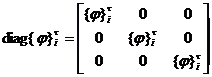
diag Φ represents the diagonal block matrix
 ( Φ is a matrix , 0 means the rest of the elements are 0 )
§ 1 General principles and solution steps
1. Variational Principle and Finite Element Method
Many physical and mechanical problems can be reduced to definite solutions of differential equations or to variational problems, that is, extreme value problems of a physical quantity . Corresponding variational principles ( such as energy principles ) point out that the two problems are equivalent For the former, the difference method can be used to approximate the solution; for the latter, a direct solution method ( energy method ) can be used . Both methods have their own advantages and disadvantages . The finite element method is a new solution method developed by absorbing their characteristics .
In variational problems, physical quantities can generally be expressed as the integral formula of undetermined functions ( such as displacement functions, temperature distribution ) and their derivatives . For the integral area Ω , the discretization method of the difference method can be modeled ( divide the grid in a certain way and Take the node ) and divide it into a finite number of sub-regions . (Because the integral expression replaces the differential expression of the definite solution problem, the division of the region is much more flexible than the division of the grid in the difference method.) For example, the desirable element is Triangle, quadrilateral, tetrahedron, even curved edge) . The value of the undetermined function and its derivative at some nodes in the subregion, called the node parameter value, obviously it is undetermined . The selection of these nodes is also more efficient than the difference method Free . On the other hand, refer to the approximation method of the direct solution method (generally take a linear combination of a class of analytic functions as the approximate solution, and the coefficients are to be determined), and use the interpolation function analytic within each (generally take a polynomial, its degree Depending on the accuracy of the calculation, its coefficient is basically determined by the node parameter value) to approximate . As long as the range of the node parameter value is appropriately expanded, the smoothness and accuracy of the interpolation function can generally be satisfied . This is more direct In the solution method, the analytic function class that satisfies certain boundary conditions is selected to be free and easy to implement .![]()
![]()
In a word, the finite element method is an effective numerical solution method developed by absorbing the idea of the difference scheme based on the variational principle . The undetermined value problem of the total number of values) . A subregion with nodes in a certain distribution and their parameter values of a certain type is called a cell .![]()
2. Application in elastic mechanics (displacement method)
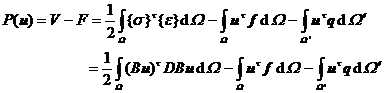
The elastic body Ω causes small deformation under the action of load f (body force acting on Ω ), q ( surface force acting on the boundary ), etc. Its deformation energy can be expressed as![]()
![]()
where { ε } and { σ } represent the column vectors ( § 5 ) arranged by the strain and stress components, respectively, and the linear relationship between them and the displacement u can be written as
{ ε } = B u { σ } = DB u ![]()
B is the differential operator matrix, D is the symmetric matrix related to the elastic coefficient E , depending on the nature of the problem . Therefore, the total potential energy of the elastic body, that is, the sum of the deformation energy and the external force potential energy, is a quadratic functional of u :![]()
The principle of minimum potential energy states that for all displacements that satisfy certain constraints on the boundary, the total potential energy caused by the displacement that maintains the equilibrium state of the force reaches the minimum value . Using the symmetry of the matrix D , it can be known that the displacement function u is the variational equation
![]()
The solution of , divide Ω into a finite number of elements , the parameter value of its node i is { u } , and assume that the interpolation function on u (each component) can be expressed as a polynomial of the same type:![]()
![]()
![]()
![]() (1)
(1)
It is called the displacement mode, in which it represents the summation of each node of the element, which is a polynomial of the coordinate variable, which depends on the shape of the element and the way of interpolation (that is , the various types of functions listed in § 2 ~ § 4 ), The number of rows and columns of the diagonal block matrix is related to the number of components of u . For example, for spatial problems![]()
![]()
![]()
![]()
is a 3 3 r![]() ( r represents the number of node parameter values for each component) matrix .
( r represents the number of node parameter values for each component) matrix .
Substitute ( 1 ) into , get![]()
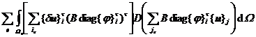
 (2)
(2)
Assume
![]() (3)
(3)
![]() (4)
(4)
![]() (5)
(5)
![]() (6)
(6)
In the formula, it represents the summation of all elements with node i . It represents the summation of all elements with two nodes i and j . When the two nodes i and j are not in the same element, ; j can also take i , then = ; in other cases, one or several units may be summed, depending on how the area is divided .![]()
![]()
![]()
![]()
![]()
The mechanical meaning of these coefficients is obvious: under the assumption of the displacement mode ( 1 ), since the node j ( including the i node itself ) has displacement, rotation, etc. deformation values generated at the node i by the action of the elastic element The reaction force * . is the so-called stiffness matrix of the element; although there are various possibilities for the number of elements including the two nodes i and j , according to the definition ( 4 ) , it can be seen that the deformation value of the node j is caused by the deformation value of the node i . Reaction force . Summation for node j in the whole area (actually only a few nodes adjacent to node i ) , the total reaction force on node i due to deformation is obtained . Similarly , the right end of ( 5 )( 6 ) The integrals respectively represent the external loads such as body force and surface force according to the displacement mode![]()
![]()
![]()
![]()
![]() ( 1 ) the corresponding external force * distributed to the i -th node through the element is simply referred to as the equivalent nodal force of the load on the element, and its sum is the total external force distributed to the node i by the entire area load . From ( 2 ) get
( 1 ) the corresponding external force * distributed to the i -th node through the element is simply referred to as the equivalent nodal force of the load on the element, and its sum is the total external force distributed to the node i by the entire area load . From ( 2 ) get![]()
![]()
![]()
![]()
![]() (7)
(7)
Except for the relevant nodal parameter values ( the variation of which is already equal to zero !) on the boundary of the part of the given displacement ( the surface force q is not given in this part ) , due to the mutual independence of each variation , the components in the parentheses ( except for the part whose variation is zero ) should be equal to zero . This reflects the objective fact that the sum of the reaction force and the external force of any unconstrained node is equal to zero , that is, the force should be balanced at each node .![]()
Finally, according to the node number of the entire area, the undetermined node parameter values are arranged in sequence , and the part that has been constrained is removed to form a total node parameter value column vector . Yes , the corresponding rows and columns are also crossed out to form a The total coefficient matrix , the so-called total stiffness matrix ( the apostrophe indicates that the row and column have been processed ) and the right column vector , so ( 7 ) can be written as![]()
![]()
![]()
![]()
![]()
![]()
Due to the symmetry of definition ( 3 ) and D , the unit is symmetric according to (4), that is , after the mth row and the mth column are crossed out, the K after the row and column processing is also symmetrical. is symmetric ; when the area is subdivided , a large number of jth nodes and ith nodes are not on the same unit, then a large number , which indicates that K is sparse . This symmetry and sparseness are the key to improving the calculation method and improving the The main basis for problem solving speed .![]()
![]()
![]()
![]()
Three, the main steps of the finite element solution
(1) Determining the variational equation or the virtual work functional equation § 5 introduces the expressions of the virtual work functional equations commonly used in the displacement method for elastic mechanics problems . When applying, it is necessary to clarify which are the undetermined displacement functions . For example, there are three spatial problems . The displacement component is an undetermined function , there are two plane problems , there is only one thin plate bending or cylinder torsion problem, etc. If the internal force distribution is not taken as the undetermined function , the corresponding variational equation should be established according to the principle of minimum potential energy . For For other definite solutions of differential equations ( such as eigenvalue problems , thermal conductivity problems ), you should refer to the discussion at the end of § 5 , multiply the variation of the undetermined solution, and use Green's formula to transform the equation into a positive definite functional form , so that the The problem boils down to an equivalent variational problem as the starting point for applying the finite element solution .
In the virtual work functional equation , the differential operator matrix B , the elastic coefficient matrix D and various load distributions ( including body force, surface force, line force and concentrated point force ) are mainly determined, so as to list the relevant integral expressions .
(2) Select the unit and divide the area . First, select the shape of the unit according to the shape and calculation accuracy of the area , and use the grid to divide the area into unit combinations of different sizes . For the part with large stress concentration or large change , the grid should be drawn so that In addition, the symmetry of the problem can be used to reduce or degenerate the fixed solution area to a low-dimensional case , so as to reduce the number of nodes and the amount of calculation . On the other hand , for non-uniform media , Grids should be placed where the coefficients are discontinuous or fractured to keep the medium coefficients smooth in each element ; and where linear forces, point forces and detection are concentrated, nodes should be placed to highlight their effects .
Secondly , according to the smoothness requirements of the problem to the solution , arrange the node and node parameter values of the element . Generally speaking , it is simpler to use basic elements for space or plane problems , and equal parameter elements can also be used , so that the boundary can be appropriately close to the area of the area. Bending the boundary to reduce the disturbance error of the boundary ; generally , the quasi-coordinated element introduced in § 4 should be used for the bending problem of the thin plate . A pair of contradictions can not only reduce the amount of calculation , but also ensure the convergence of the solution .
In addition to the requirements of § 2 and § 3 for the shape of the element , it should be noted that its vertices cannot be used as interior points on the edges of adjacent elements , and the mesh should be as regular as possible to reduce the amount of calculation .
Finally , referring to § 2~ § 4, determine the shape function and displacement mode corresponding to the same node parameter value , and for complex elements, the undetermined coefficient method can also be used to directly use the polynomial coefficients as generalized node parameters for element analysis .
(3) The element analysis replaces the original undetermined function with the interpolation polynomial , and the quadratic functional of the total potential energy of each element is discretized into the quadratic function of the node parameter value , that is, the original variational equation is discretized into the algebraic equation system , Its coefficient matrix is the stiffness matrix of the element . This work is the key to the discretization of the problem , because the total potential energy of the entire region can be approximately regarded as the sum of the total potential energy of each element . Obviously, it is also discretized into two of the total node parameter values. Therefore , the main content of element analysis is to calculate its coefficient ( stiffness ) matrix and equivalent function value ( nodal force ) according to the geometric and mechanical information of the element . ![]()
![]()
![]()
![]()
![]()
![]()
![]()
According to the definition of ( 2 ) and ( 3 ) , the elements of the stiffness matrix are actually the coefficient blocks of × , which are the number of parameter values of the i -th node . For example, for space problems , an equal- parameter element can be used , and B is 6 × The first-order partial differential operator matrix of 3 ( see formula ( ) ), , diag is a 3 × 3 diagonal block matrix , so![]()
![]()
![]()
![]()
![]()
![]()
![]()
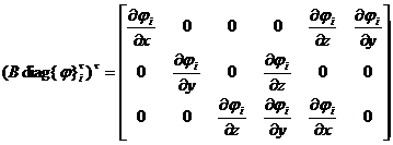
is a 3 × 6 matrix, and D is a 6 × 6 elastic coefficient matrix ( see ( 31) ) . Substituting into ( 3 ) is not difficult to obtain a 3 × 3 coefficient block
![]() (k,m=1,2,3)
(k,m=1,2,3)
in
As long as ( 1, 2, 3 ) and ( x, y, z ) are cyclically replaced at the same time, the others can be obtained . Obviously, the element stiffness matrix is symmetric , because . Note that for the thin plate bending problem , due to the quasi-coordination element, the number of parameter values of each node is not necessarily the same ( see § 4 ). In this case, the undetermined function has only one deflection , diag = is a 1 × matrix , and B is changed to a 3 × 1 second-order partial differential operator matrix , so it is The matrix of × 3 is substituted by the function of the type of nodes i , j ( 3![]()
![]()
![]()
![]()
![]()
![]()
![]()
![]()
![]() ) formula can also obtain the integral formula of the coefficient block . For example , the type functions of nodes i and j are , , then =3 , =1 and according to the corresponding B and D formulas, there are
) formula can also obtain the integral formula of the coefficient block . For example , the type functions of nodes i and j are , , then =3 , =1 and according to the corresponding B and D formulas, there are![]()
![]()
![]()
![]()
![]()

in the formula
This is a 3 × 1 coefficient block . Once the type function is determined, it can be substituted into the integral value . If the interpolation polynomial coefficient is used as the generalized node parameter , all the type functions of the element should be changed to the integral obtained by the terms of the polynomial. The value is not the coefficient block, but the generalized coefficient matrix of the whole unit and the equivalent node force , etc. For this , it must be converted to the above form according to § 4 , in order to follow ( 4 ), ( 5 ), ( 6 ) summation .![]()
![]()
![]()
For the physical force f and the surface force q , their equivalent nodal forces can also be obtained according to equations ( 5 ) and ( 6 ) . Then the corresponding equivalent node force should be added :![]()
All of the above numerical integrals can be calculated by standardized procedures ( see appendix ). However, it should be noted that the median function takes more local coordinates , and the differential operation is on the global coordinate system ( x, y, z ), so it is necessary to calculate the product They must be transformed into a unified expression of the local coordinate system through coordinate transformation ( see § 2~ § 4). In addition , when calculating the integral value of each element , the node number can generally be local ; but when participating in the overall synthesis , the local serial number of each element node must be changed to the overall unified label , because in the sum formula of ( 4 ), ( 5 ), ( 6) , i , j can only be the overall label of each node .
( 4 ) Treatment of boundary conditions and overall synthesis In the previous section, only the case of pure load support is considered . If elastic supports and geometric constraints are given to some boundaries , necessary treatment must be carried out before participating in overall synthesis . In fact , it is these Only the conditions guarantee the positive definiteness of the coefficient matrix and the uniqueness of the solution .
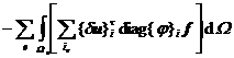
Assume that in the space problem, some boundary of Ω is elastic support , its elastic coupling coefficient is a positive definite matrix of 3 × 3 , and the displacement value is given to the other part of the boundary . In this way , in the variational equation ( 2 ) there is one more formula![]()
![]()
![]()
![]()
![]()
The integral term of the surface force q along the edge is missing, because the upper q has no contribution to the total potential energy . Due to the space problem , , the coefficient block should be changed to the elastic support part , where![]()
![]()
![]()
![]()
![]()
![]()
As for the constraints, the coefficient matrix should be divided into rows and columns . The principle is as follows:![]()
Assuming that the overall labels of the nodes that fall on the region after division are , , … , , according to the constraints , ( n = 1 , 2 , … , ) . The equation has been naturally satisfied , so it is not necessary to list it . In this way , the coefficient matrix of equation ( 7 ) is crossed out the coefficient block ( n = 1 , 2, ... , , ) or the corresponding 3 rows ; Substitute the displacement value of ( 7![]()
![]()
![]()
![]()
![]()
![]()
![]()
![]()
![]()
![]()
![]()
![]()
![]()
![]()
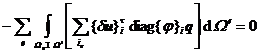
![]() ) and move the part in the formula to the right side of the equation , so that the coefficient blocks of the first , , ..., columns or the corresponding 3 columns are crossed out . ( 7 ), the specific column formula can be expressed as
) and move the part in the formula to the right side of the equation , so that the coefficient blocks of the first , , ..., columns or the corresponding 3 columns are crossed out . ( 7 ), the specific column formula can be expressed as![]()
![]()
![]()
![]()
![]()
![]()
![]()
![]()
![]()
which is still calculated according to ( 5 ) , and the formula ( 6 ) should be changed to![]()
![]()
For the thin plate bending problem, the boundary conditions are more complicated, but the principle is the same .
If there are also thermal effects, the thermal equivalent load can be added to the element's equivalent nodal forces as part of the body force, depending on the nature of the problem .![]()
After these treatments , and then by ( 4 ), ( 5 ), ( 6 ) equations summation can be obtained about all the nodal parameter values of linear equations , the overall synthesis is over . program to achieve .
( 5 ) Numerical solution of equation system The coefficient matrix of the equation system is generally positive definite , which ensures the uniqueness of the solution . In addition , it has symmetry and sparsity . As long as the node labels are properly adjusted, the non-zero coefficients can be concentrated in the The vicinity of the main diagonal of the matrix forms a "band matrix" , and these properties can greatly save the calculation and storage amount of the solution . There are two main types of numerical solutions to this type of linear equation system , namely the iterative method and the direct method .
Finally , it is necessary to synthesize and analyze the calculation results . For example, according to the solved parameter displacement value, the stress distribution of the element or node is obtained , and the drawing list is analyzed and so on .